Fuel sender unit access panel
As everyone knows the fuel tank sender unit on the Type 2 is notoriously inaccessible being on top of the fuel tank, which in turn is behind a panel (on most bus’s) which in turn is behind the engine.
This means that if the sender unit fails you can do one of two things:
Fill your bus up with fuel at frequent intervals in an attempt to avoid running out.
Remove the engine, tank panel, tank and then replace the sender unit.
OR
You can fit an access panel in the floor area over the tank.
Safety
This operation involves cutting, drilling etc in the fuel tank area so I personally would not advise doing this when the fuel tank is in place. In theory it is possible to do with the tank still fitted BUT I WILL NOT RECOMMEND IT.
As always, wear the correct safety equipment.
I did this as the tank was already out as there were repairs to be done to the tank strap mounts and the tank was removed for stripping and painting.
So, lucky ol me, there’s bags of space to work.
Now, the first thing to do, obviously is to get the hole in the right place and the right size.
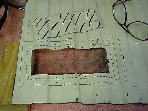
As the sender unit is roughly in the center of the tank and the tank is roughly in the center of the bus then I guess that’s where the hole goes. I took measurements from the lip at the rear of the rear floor area and across the front edge of the floor as shown in the diagram below:
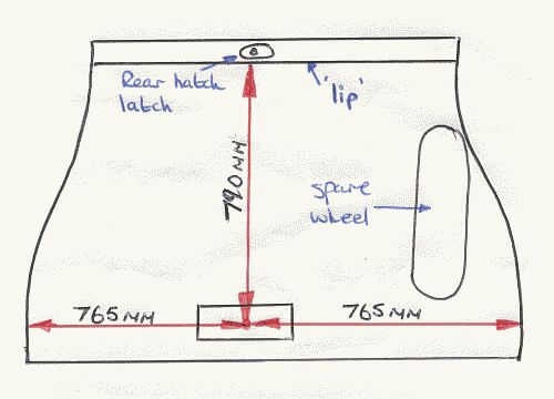
These dimensions are OK to the nearest 5 mm or so.
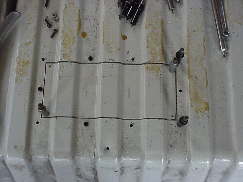
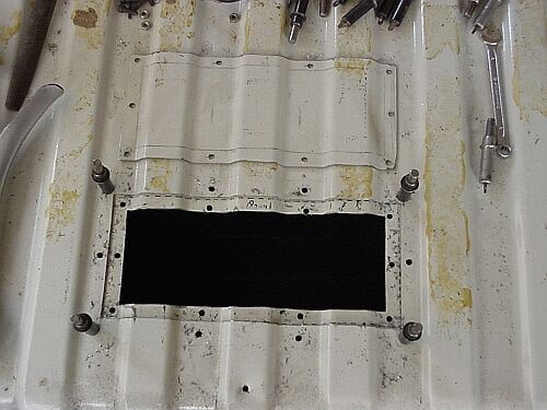
The hole is 200 mm x 90 mm and should be positioned so that it looks like this:
You will notice that the hole is positioned so that is runs from the ‘dip’ on the left to the ‘dip’ on the right, this is for a reason as you will see later. It allows the fixing bolts or screws to be fitted in the ‘dips’ in the floor so that they do not foul the floor covering and if your mattress is a bit thin it’ll stop em stickin in your back!!
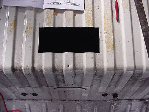
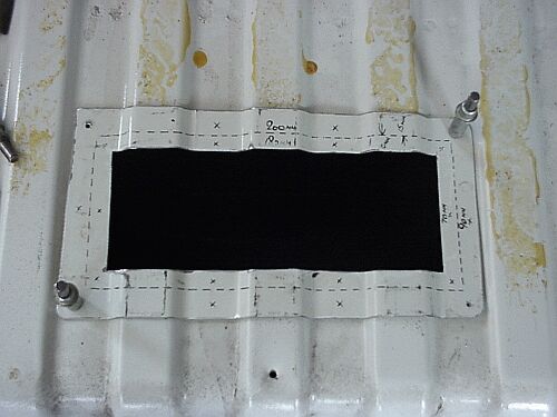
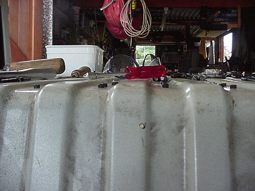
Here’s a general view, from this you can get a pretty good idea of where the hole is.

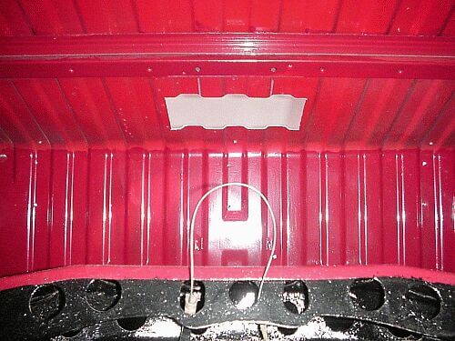
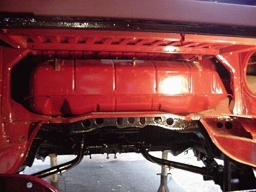
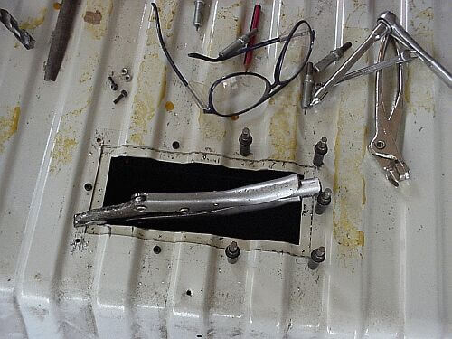
Here’s a view from the engine bay looking up into the fuel tank bay
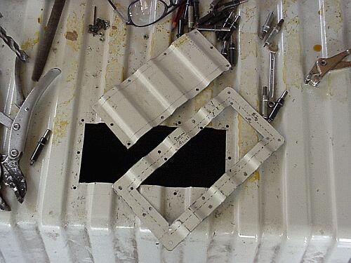
Here’s the missing bit.
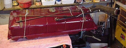
So, lets just slot it in and see how much access this hole really gives you. (As you can see, I’ve removed all the pipes so it’s easy to get in and avoids damage to the pipes.
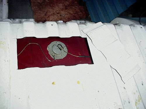
Here’s a view from the top to show how much access you get.
Ahh, something I forgot to mention, what are you going to use to fill the hole back in? I used a jig-saw with a thin blade so I can use this as the actual panel but as I am going to fit a panel landing or ‘butt strap’ (ouch..oooeeerr) I need something with the same ridges as the floor section and before you say floor panel, it ain’t the same. What I did was nip down to my nearest bus dismantler and asked him to cut out a large section of the rear floor of a bus that was going to be scrapped (sad but there you go).
I did this well in advance so that as soon as the guy had got the appropriate bus and cut the floor out I could just go and pick it up and start working. This also means that if you make a complete hash of cutting the hole and wreck the panel cover you have cut plenty of metal to make a new one.
At least this means that part of that bus will fly again.
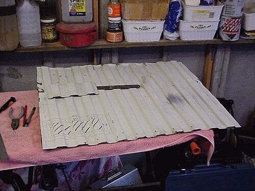
Below is a picture of the dimensions of the butt strap (I’ll call it the landing from now on) drawn on the floor panel prior to cutting.
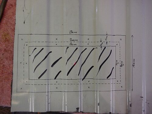
The dimensions are:
Along the top, 180 mm, 200 mm, 230 mm.
Along the RH side, 70 mm, 90 mm, 120 mm.
Now cut the middle bit out. Note the safety glasses, cool huh!!
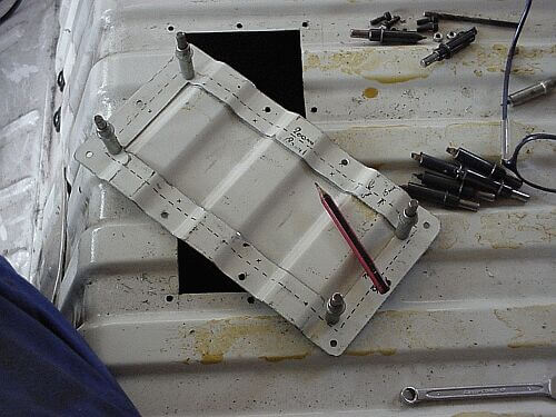
Right, now I’ve cut the complete landing out and have carefully positioned it over the hole so that the dotted lines you can see line up with the edges of the hole underneath.
I have pilot drilled the corners and fitted gripper pins to hold it in place. OK, gripper pins, these are things used to hold bits of metal together through holes and are absolutely brilliant. The aircraft industry would come to a grinding halt if it wasn’t for these little beasties. As you may appreciate, I once serviced and then built aircraft and as you all know bits and pieces fall into your tool box.
An alternative to gripper pins I hear you say, well, you can drill the holes slightly larger and use small nuts and bolts.
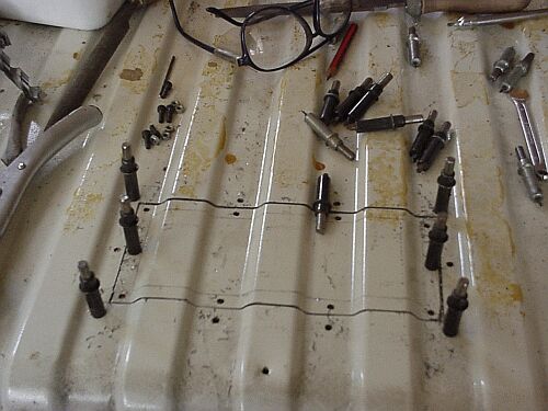
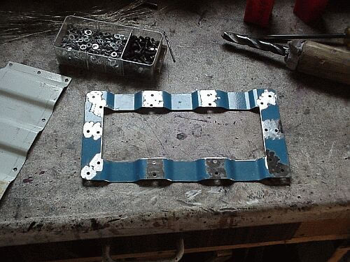
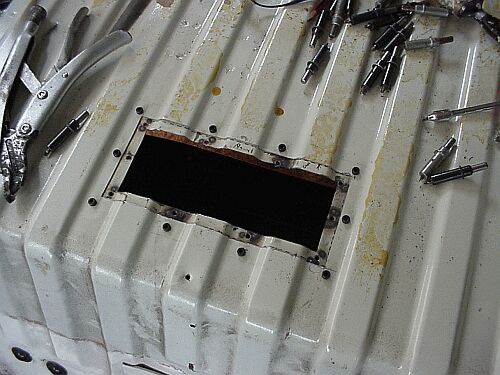
After drilling the four corner holes the landing can now be fitted underneath the hole and the rest of the pilot holes drilled.
You can see here that I have only drilled holes in the ‘dips’ of the floor panel.
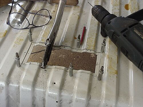
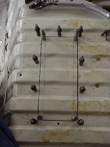
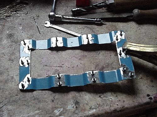
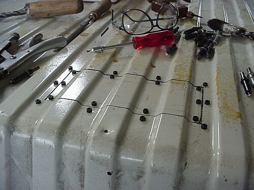
In the next picture I have started to drill the holes out to full size and have pinned it in place with larger gripper pins, yes they’re colour coded!!. I have also fitted bolts at the other end to show that the same can be achieved. The bolts are 4 mm allen or socket head screws and are about 10 mm long.
Once the outside holes have been drilled to full size, the inner ones need to be pilot drilled,so I dropped the panel into the hole, lined it up and carefully pilot drilled each corner.
Then I took both parts out of the panel and fitted the access panel under the landing so that I could mark the outline of the hole on the access panel.
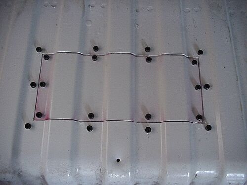
Next I put it all back together again and here you can see the marks where the outline of the landing is on the access panel and the crosses where I am going to drill these holes.
Here we can see all the holes drilled out to full size
And here you can get an idea of what the finished item will look like.
Landing removed as well
Now it’s off to the workbench to prepare the landing for welding. Here I have cleaned up the areas around the holes on the BACK of the landing.
The next picture isn’t very good but it shows the nuts being held onto the back of the landing with the bolts.
And here’s a shot of all the nuts welded into place.
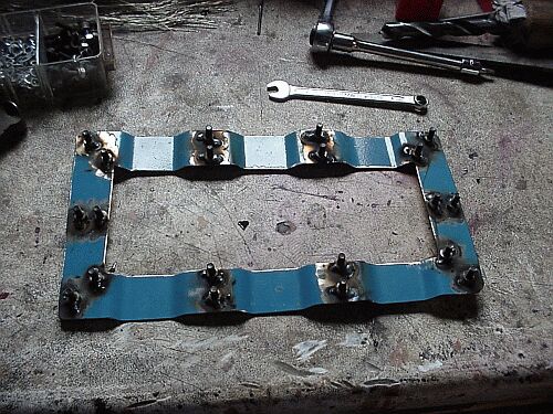
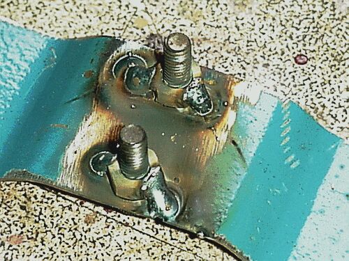
And a closeup of the welding. It’s worth practicing the welding of small nuts onto thin plate as you’ve only got one shot at this. Also check all the bolts afterwards for weld spatter as it can strip the thread in the nuts if you’re not careful. I have in the past sprayed the bolts with anti-spatter spray before assembly but found that some can get onto the nut or the plate and causes a bad weld so I do it dry and go careful.
OK, lets have a dry run at this, first fit the landing.
You may be asking why I didn’t just rivet the landing in but I thought that if I bolted it in then it can always be removed to give that extra bit of space.
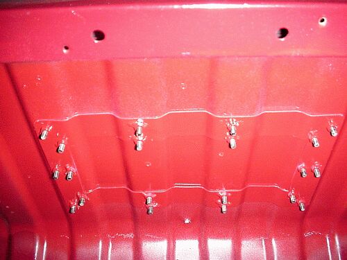
And the access panel fitted.
The next picture shows why I put all the bolts in the ‘dips’ in the floor. You can see (barely) that the bolt heads are all below the level of the floor panel that would be fitted over the floor area.
OK, dismantle it all, clean it up and spray the components.
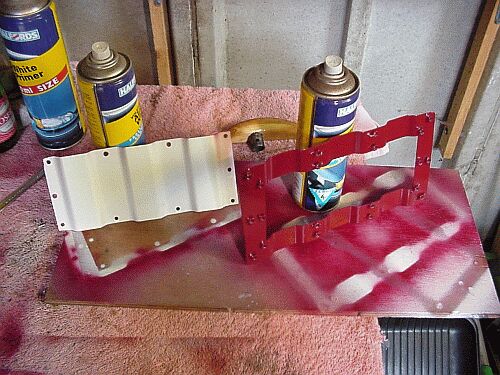
And just fit it in place.
Even from underneath.
Original location:
http://www.specialpatrolgroup.co.uk/spooky/access/access.html
This web page was posted at the link above but the website is no longer online and I was unable to track the owner down. I felt this web page was too good to disappear.
Learn more about my Revival project, any questions let me know.