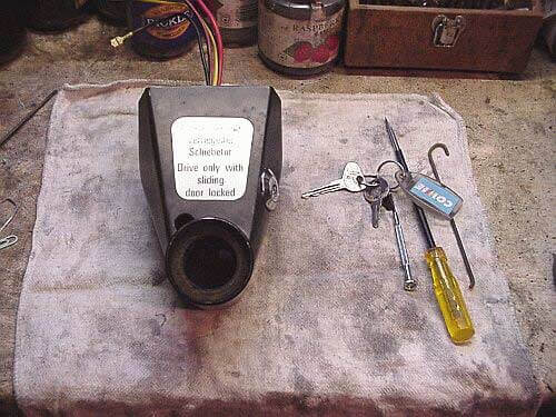
Ignition barrel replacement
The ignition barrel on Type 2’s is notoriously fiddly to replace, it was designed to be fitted easily but not removed, but if like me your key is so old and worn that it is in danger of breaking then something needs to be done.
Keys can be cut by those suppliers who have the correct tools to do them and you have the key number handy, otherwise it would need to be cut on a key copying machine which could not be done in my case as the key was extremely worn and the copying process would produce a defective key.
Please read this complete section before attempting this job as understanding the construction of the ignition switch/barrel is essential to replacing it with the minimum amount of grief.
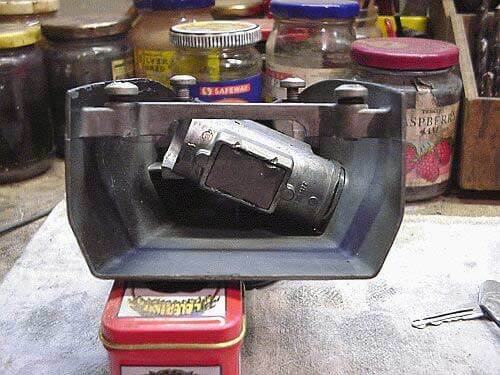
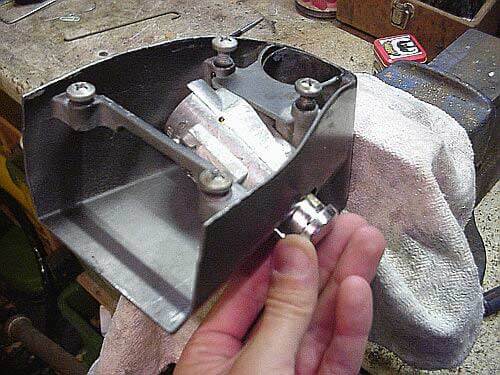
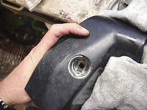
This is the stage you should start at, with the steering column removed and the ignition switch boss removed. Haynes and Bentley both describe the steering column removal process.
It is not absolutely necessary to remove this from the bus but in order to fit the new barrel two hands are required and working upside down under the dashboard is not easy!!
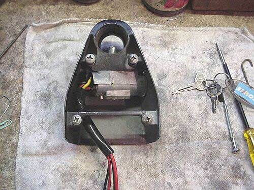
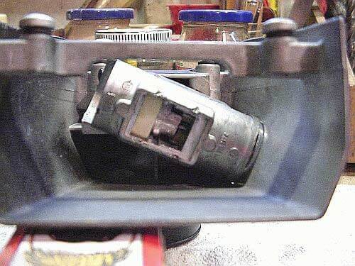
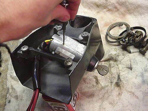
Here it is turned over and you can see the block fitted to the boss with the ignition switch on the left.
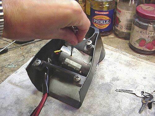
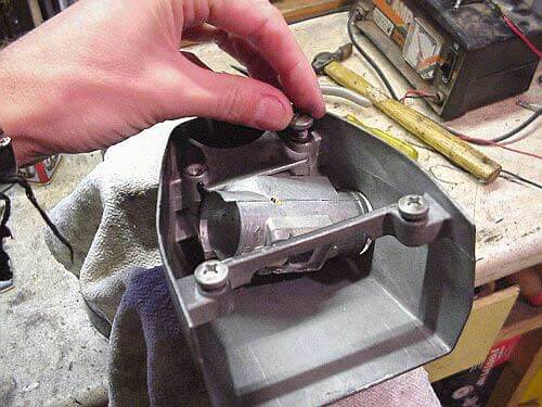
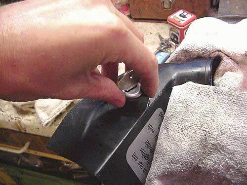
Here I am removing the small (and I mean SMALL) ignition switch locking grub screw from the block. This is another reason for removing the boss from the bus, this screw is virtually guaranteed to fall out and vanish into the ether never to be seen again.
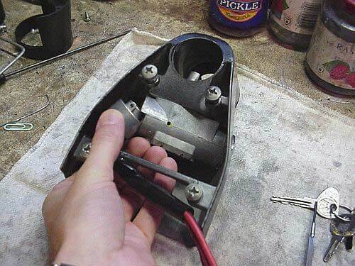
Here, the ignition switch is carefully being removed, this is a tight fit and care is needed to avoid damage to the wires.
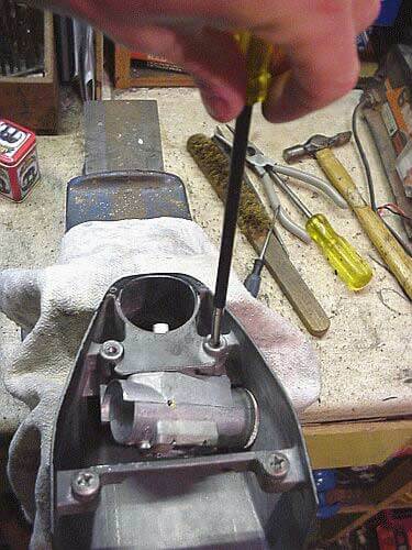
Now I’m looking in the end of the boss and you can see a cover which allows the internals of the steering lock to be removed, remove the cover by carefully removing the peining Don’t remove the internal parts.
Here, the cover is removed and you can see the nylon block on the left and in the center, the steering lock mechanism, when the barrel is removed these two part spring apart (don’t worry they won’t fall out) and will not allow the new barrel to be fitted unless they are pushed together again which I am sure would be near impossible with the boss still in the bus.
The magic tool, a ‘J’ shaped piece of wire. This needs to be quite stiff and not too thick, mine is probably 1.5 mm thick and it was tight in the hole.
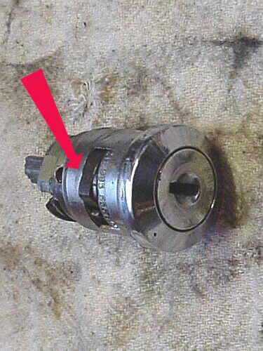
The barrel, when fitted has a spring on one side which as the barrel is slid into the block springs out into a channel in the block which prevents removal. The access hole to release the spring is of course in the most awkward place, behind the block.
If you have your new barrel ready offer it up into the same position as the old one and you will see where this spring lies.
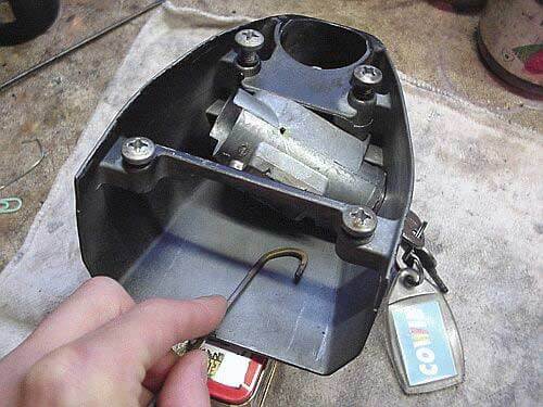

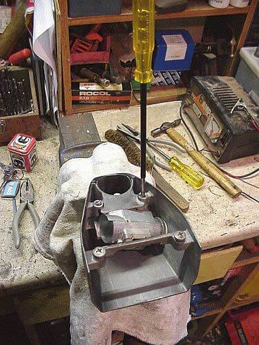
Here I have the ‘J’ wire in the hole and am pulling it towards me and at the same time gently levering the old barrel out of the block, you will find that if you have the ‘J’ wire in the correct position and the spring is compressed then the barrel will come out very easily, if there is any resistance then the spring is probably not compressed enough.
This is the most fiddly part of the whole job and I found that the stiff brazing rod allowed me to ‘feel’ the spring being compressed. I tried with a paper clip but found that it wasn’t really stiff enough to compress the spring and bent.
As you can see here, once the spring has been compressed and moved away from it’s detent the barrel almost falls out.
Now to remove the block from the boss. This is only necessary if you need to replace the block otherwise all other operations can be carried out without removing it.
I am removing it to show where the spring release access hole is.
First remove the boss retaining bolts (if not already removed)
Next remove the two grub screws that are fitted at the bottom of the retaining bolt holes.
The block will now fall out.
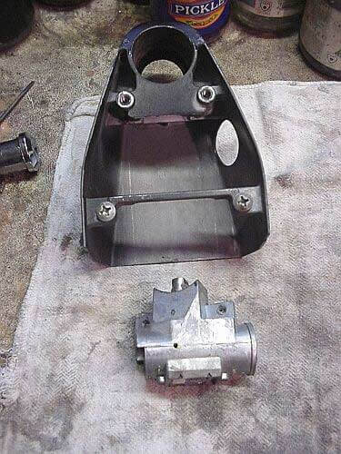
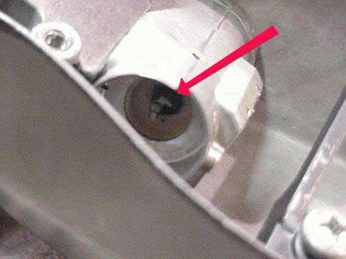
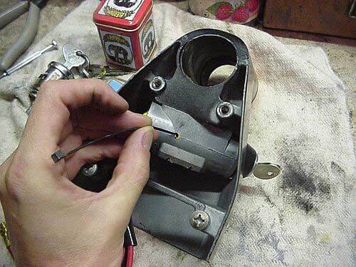
If you now roll the block towards you, you will see the spring release access hole as indicated by the arrow.
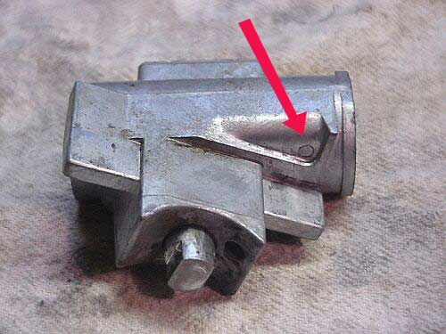
Here is the barrel in the same orientation as the block above showing how the spring lines up with the hole.
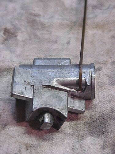
Here you can see the ‘J’ wire inserted into the hole.
Reassembly is the reverse of removal, first fit the block and the two grub screws.
Now, it is time to fit the new barrel.
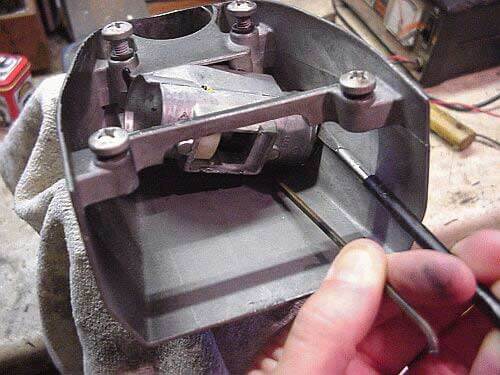
If you look into the hole this is what you will see and it is obvious that the new barrel will not go into this hole as both the steering lock and it’s nylon block have sprung apart blocking the hole which the ignition switch operating rod goes through.
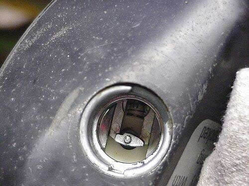
Here I have compressed both the steering lock and nylon block so that the hole is no longer obstructed, the springs are very light and finger pressure is all that is necessary.
This is why I believe it would be very difficult to do this job with the boss still in the bus as to gain access to the nylon block the small metal cover needs to be removed which is hard enough in the vice let alone attached to the steering column. Also, the steering lock needs to be compressed and as it is inside the steering column, there is no way you’ll get your fingers in there.
With the steering lock and nylon block compressed, line up the locking spring on the new barrel with it’s indent in the block and gently push it in. It will go in very easily and you will hear the spring locate in it’s detent. Incidentally if you have forgotten anything, the only way to remove it is with the ‘J’ wire.
With the new barrel inserted and locked into place you can fit the ignition switch. This, as with removing it must be done carefully as there is not much space and a fair bit of jiggling is required. Below, the arrow indicates the ignition switch operating rod.
Now fit the little grub screw that you didn’t drop ensuring that the hole lines up.
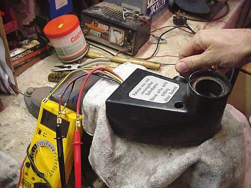
Here I am testing the switch to make sure all works OK.
There are four wires to the ignition switch, red, red/black, yellow/black and black.
The red is the supply from the battery. When the ignition is switched on power is then supplied to the yellow/black wire and the black wire. When the key is turned to the ‘start’ position power is supplied to the red/black wire, power is disconnected from the yellow/black wire and power maintained to the black wire.
The yellow/black wire supplies such things as lights, wipers etc. The black wire supplies essential services such as the hazard flashers. The red/black wire is the supply to the start motor so when the key is turned to ‘start’ power is denied the lights, wipers to relieve stress on the battery but still maintaining a supply to the ’emergency’ services and of course supplying power to the start motor.
Last thing, you don’t want that pesky little grub screw dropping out so put a small dab of paint on it.
Now you can reassemble the steering column.
Original location:
http://www.specialpatrolgroup.co.uk/spooky/barrel/barrel.html
This web page was posted at the link above but the website is no longer online and I was unable to track the owner down. I felt this web page was too good to disappear.
Learn more about my Revival project, any questions let me know.