How to replace the For Ka lambda sensor
This little Ka was jumping all over the place, it had the following symptoms :
-
- Massive fuel consumption – 1/2 a tank to go 30 miles
- Stuttering and loss of power
I did some research and decided that the lambda sensor could be the problem, but that’s still a bit of a sore point for me.
Replacing the lambda sensor didn’t sort the problem for me, turns out the coil pack had packed in. A call to my local Ford parts department and they wanted £150 for a new sensor.
Quick trip to the local eurocarparts, who sent me to a branch 10 miles away, who in turn sent me to a branch 5 miles away and I purchased a universal 4 wire lambda sensor saving myself about £90.
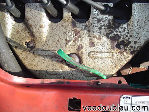
Step 1 – Where is the lambda sensor
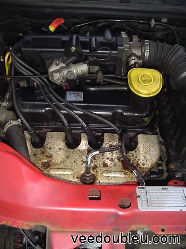
The Ka is different from most cars, well in most cars I’ve seen anyway, in that the lambda sensor is easy to get at. Most cars the sensor is attached to the exhaust somewhere underneath the car and you need to jack it up to get at it, not so with the Ka.
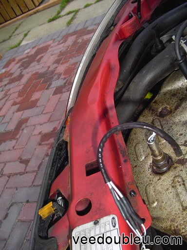
All you do is open the bonnet and its right in front of you. Its right in the center of the heat shield looking like a lonely spark plug.
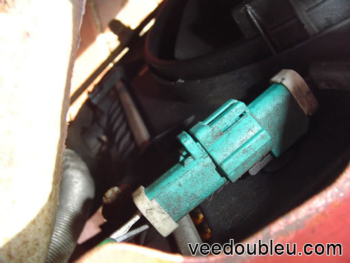
Step 2 – Unclip the connector
One end the Lambda sensor is screws into the exhaust manifold. At the opposite end of there is a green plastic connector. The first thing you need to do is carefully unclip this as you will need it later.
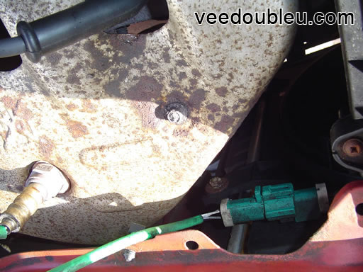
Step 3 – Unscrew sensor
Our Ka had been unloved for many years, due to family circumstances it had been sitting unused for almost two years. Because it sat unloved for so long and because of its age (1999) lots of parts, bolts,nuts and screw heads have rusted away or seized on. The lambda sensor was no exception.
You need a 22mm spanner or socket to loosen the sensor. Or in my case a 22mm socket, half a can of WD40, some snips, a hacksaw and a hammer.
If your sensor comes out easily you can skip step 4 and jump to step 5.
Step 4 – Problems ?
If your reading step 4 then like me you have problems removing the sensor you might want to try my brutal method.
-
- Carry out steps 1 and 2 as normal
- Remove the heat shield for easier access, you don’t have too, but it makes things… well… easier.
- Saw through the metal of the sensor at the level shown on the destroyed sensor below.
- The center of the sensor is ceramic which you won’t be able to saw through so keep sawing until you feel the blade slipping. Do this all the way round.
- Tap the the sensor above the saw line like your playing croquet slowly increasing the force until the top drops off. Well, pings off at high speed.
This probably isn’t the best method in the world but it worked for me.
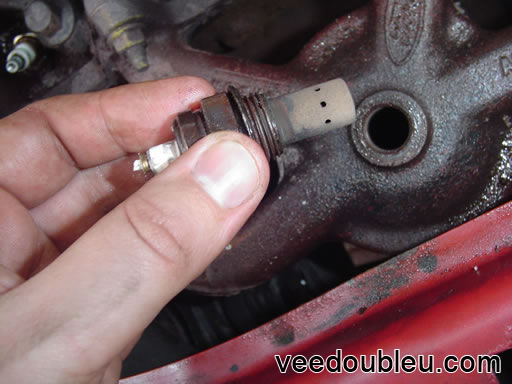
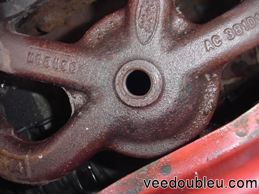
Step 5 – Exhaust manifold
You should now be looking at something like this. If you skipped step 4 your heat shield will still be in place, either way the hole in the center of this picture is where the sensor came from.
You’ll be glad to know the next step can be done inside…. where it’s nice and warm, this is where you can use your dirty hands and the fact your fixing the car to blackmail your wife/husband/parent/partner of favorite child into making you a cup of tea…… and maybe a wee biscuit.
Step 6 – The wiring and a cup of tea
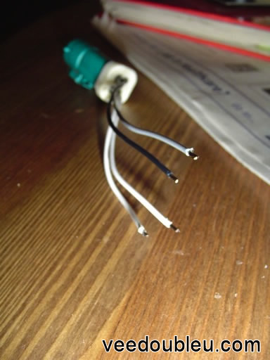
If you purchased the part direct from ford (or if it came with the connector attached) you can skip to step X, just pop in the new sensor and your done. If your cheap like me then there is a little more work to be done.
The sensor I bought came with instructions in Greek, Spanish, German and something resembling English. The picture above shows the clip salvaged from the original sensor with about 5mm stripped at the ends. The new sensor came with the wire pre stripped.
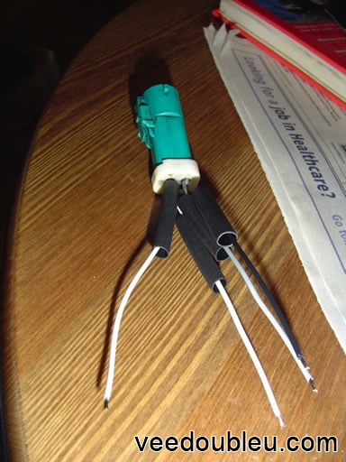
Step 7 – Preparing to join the wires
Its pretty important that you put these sleeves over one end of the the cable before you join them together. They shrink when heated protecting the joins.
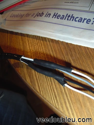
Step 8 – Joining the cables
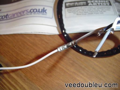
The image above shows the the cable ends are inserted in each end of the metal connector then all you need to do is use snips or pliers to squeeze the connector which holds the wire in place.
The cables need to be matched to the correct colours, in the Ka there are two white cables, it makes no difference which one you connect to which.
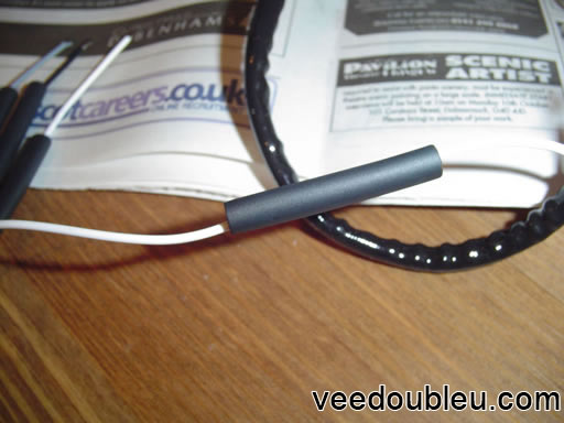
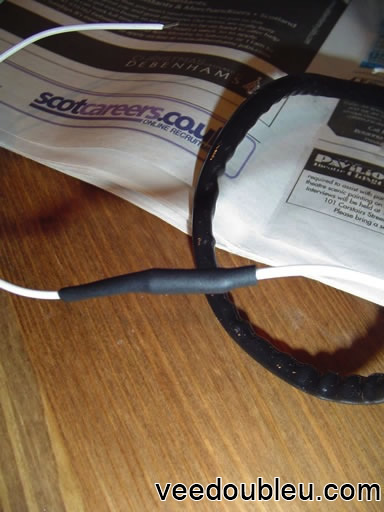
Step 9 – Protecting the cables
Slide the plastic sleeves over the join you have just created (aren’t you glad you read step 7 🙂 ) and zap them with a heat gun or a hairdryer shown in the pics below.

Step 10 – Re fitting the sensor
Fitting the senor is easy, just a case of screwing it back in at the correct torque (which I’ll need to look up, can’t remember off the top of my head).
And that ladies and gents is how you change the lambda sensor on a Ford Ka.
So that’s it, if you use this guide or have any questions or comments please contact me and let me know.
For more Ka guides have a look here.