Retro fit cruise control
There follows below, a detailed ‘how-to’ for the retro-fitting of Cruise Control into the VW Golf Mark 4 (MK IV) TDi.
Although this procedure is specific for my model of Golf: the GT TDi PD130, it is probably also applicable for other TDis, and indeed other petrol models with ‘Drive-by-wire’ throttle, and a pre-installed clutch pedal switch.
UPDATE! It has been brought to my attention by a kind fellow VW owner, that this mod can be facilitated for Petrol VW Golf / Bora and maybe also others with Drive By Wire throttles.
It involves the addition of some extra wiring which is perhaps missing between the bulkhead connection socket and the ECU.
The wiring schematic showing the loom is here ( This will open in a new window. it’s too big for this page )
These wires can be sourced from a breakers yard for a few pounds.
The information listed on this website is given in good faith, it is supplied ‘as-is’. No responsibility is accepted for any damage arising from following this guide.
Tools needed
-
- M12 Spline Drive (for the steering wheel bolt)
- 4mm Flat-Blade screwdriver (long reach)
- Philips screwdriver (medium point)
- Philips screwdriver (small point, long reach)
- Torx drivers: T15, T20, T25, T30
- Torch
- Sockets: 10mm, 13mm
- Ring/open ended spanner: 10mm
- Sticky tape (electrical)
Volkswagen Parts
-
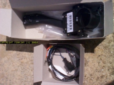
- Replacement Indicator Stalk Switch with cruise control
Part number: 1J0 953 513 01 C - Additional wiring loom for cruise control switch
Part number: 1J0 971 425
- Replacement Indicator Stalk Switch with cruise control
Total cost as of May 2002: £56 GBP inc. vat. (Be aware that the wiring loom is usually on a week or two back order)
Procedure
First step is to do the internal switch swap – just in case you have to do the job over several days, and want to use the car between.
These steps in best order are
-
- Cruise- Stalk
- Work- Outside – For the second step it is best to do the outside next.
- Wiring- Inside – For the third step you could do this alongside the external works – I did.
Work on the new stalk switch
It all starts by getting the steering wheel off !
1) Removing the airbag and wheel
DANGER: The steering wheel contains an air-bag module. Seek the guidance of specialists if you are unsure about handling this device!! Do not sit in front of the airbag whilst removing, nor let anyone else sit inside the car.
Turn the steering wheel 90 degrees from the ‘straight ahead’ position.
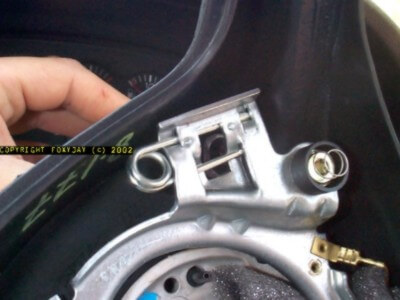
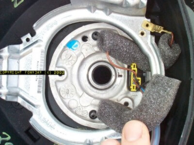
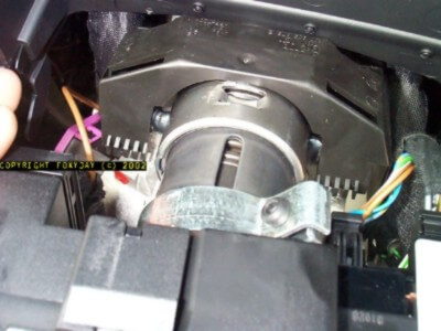
Using a mirror if required, look at the back of the steering wheel hub; the bit now facing the speedo binnacle area.
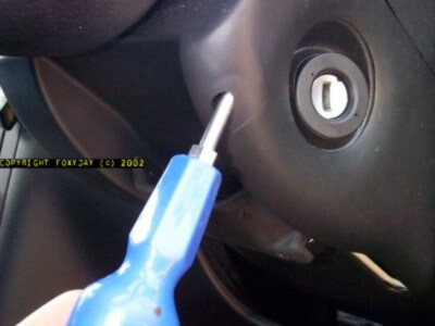
Insert a long, small screwdriver (flat), and you’ll now have to lever open one of the retaining springs. (It’s easier to see what you’re levering, by looking at the inside view below)
By levering upwards on the screwdriver handle, the tip will go downwards and the spring will open, allowing the airbag module retaining peg to be released.
Rotate the steering wheel back through 180 degrees, and repeat this process on the second and final securing spring.
Carefully, now remove the airbag module far enough to un-clip the firing line wire (5cm or so)
Lay the airbag module somewhere it won’t get knocked or dropped (like on the back seat of the car). It can ‘fire’ if dropped, or be made inert.
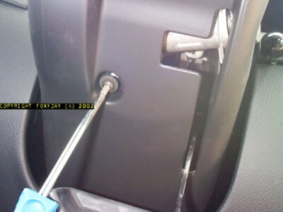
Return the wheel to ‘straight ahead’. Using the M12 spline drive, and whilst holding the wheel tightly (not against the steering lock), turn the center fixing bolt out, anti-clockwise.
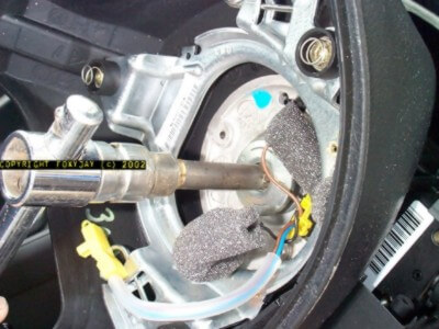
Now look at the bolt seat area on the top of the steering column – there should already be an alignment mark – if not, be sure to punch one. (the splines are very fine, so be accurate with marking)
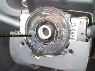
The wheel can be removed by pulling gently towards you. Note the location of the contact ring/indicator cancelling device wheel engagement peg, and remove this item by un clipping.
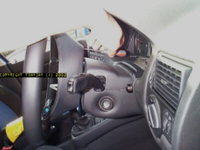
Remove the plastic shrouding around the steering column by un screwing the small Philips head securing screws in the deep recesses and the large exposed torx bolt under the ignition switch.
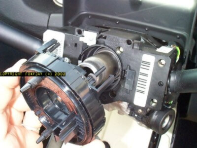
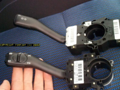
2) Removing and Replacing the Stalk Switch
The stalks are both mounted onto the column as a unit, and need to be removed together.
Slide out the steering column adjustment to give better access here if required.
Slacken the unit mounting clamp bolt (black torx head on the shiny metal clamp in RH pic). Withdraw the stalk unit, and when accessible, un clip the loom plugs on both sides. The entire unit can be moved now and be split-down.
Insert a small flat-blade as shown, lever the clip, and slide the two halves apart.
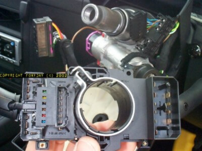
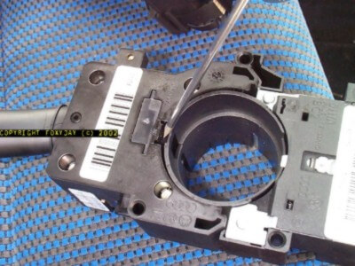
Retain the wiper stalk half, and slide-in the new cruise-control stalk to replace the original, until it ‘clicks’ securely home. Get the new wiring loom, and insert the 10-way black plug at one end, into the socket on the back of the new CC stalk unit.
Re-assemble the stalk assembly back onto the column, plugging the two main loom connectors in reverse order of removal.
Carefully thread the new loom wiring alongside the other wiring, down beside the steering column and push the ‘loose end’ and the slack wire into the ‘behind dash’ area, ready for the next stage.
Clamp-up the stalk switch unit to the column shaft with the torx driver.
Re-fit the column plastic shrouding.
Refit the indicator cancelling unit.
Carefully re-align and refit the steering wheel, noting the alignment marks.
The wheel fixing bolt can apparently be removed/refitted up to five times before needing replacement.
Carefully offer the airbag module up to the wheel, refit the firing line wire, and re-clip the module pegs back into the spring fixings.
Test everything disturbed to ensure it’s all safe.
Work outside the car.
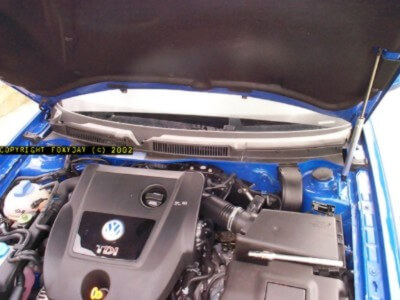
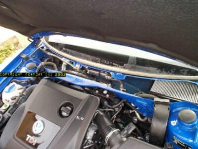
1) Removing the scuttle panel
Open the bonnet fully, and get a good look at the gear below the windscreen. The black plastic running the entire width of the car must be removed.
Not too tricky, but there’s a trick to every step!
With the wipers at natural rest position, use a small piece of electrical tape stuck to the screen each side to mark the position (believe me, it’s invaluable).
Prize off the caps covering the wiper arm securing nuts. It’s a 13 mm socket you’ll need to remove the nuts.
The arms are secured onto splined shafts, having a tapered shoulder, so they do ‘set’ very tight.
At this point, I closed the bonnet, lifted a wiper arm, and wiggled towards and away from the screen until it freed. Remove both arms and set aside, remembering which is which side.
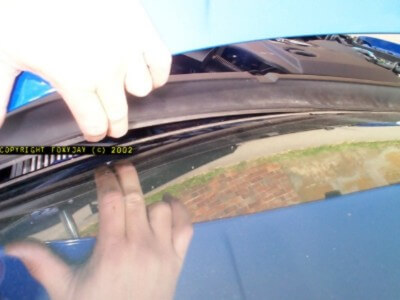
Now remove the rubber seal at the junction of the bulkhead and the plastic scuttle.
The plastic scuttle is next. This is securely clipped into the lower edge trim of the windscreen.
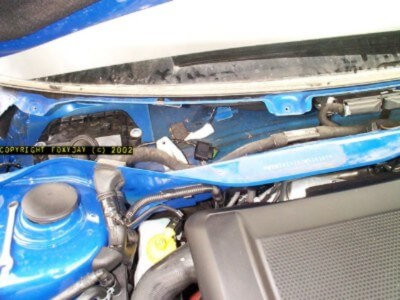
To remove, first get your finger under the top edge, and work your way along, releasing it (in the direction perpendicular to the screen). Carefully ease it out of position, over the wiper arm shafts and set it aside.
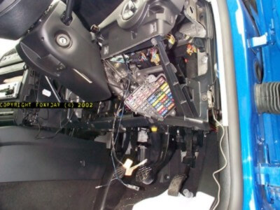
Looking at the open space now, you can see the cabin air filter to the right side, the ECU in the center, and wiper mechanism to the left.
2) Removing the wiper mechanism
The wiper mechanism obstructs the cable socket box cover, so this has to be removed.
This is fixed in place with three bolts, 10 mm size. Undo all these and remove, then unplug the wiper motor cable.
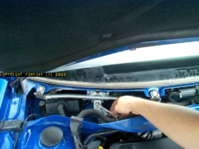
Carefully manoeuvre the wiper mechanism out of the space and set aside. This will give complete access to the cable socket box cover.
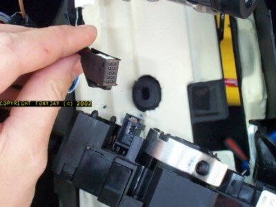
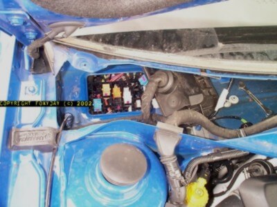
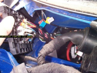
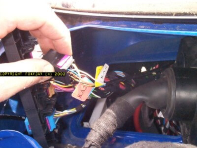
3) Accessing the cable socket box
Now remove the two pressed nuts holding the cover of the cable socket box – these are 10 mm.
Slide the cover to one side and unplug all the sockets. The only socket involved in this project is the black one.
If you can get to this from the inside as well, then unclip and drop the socket back in behind the dash, ready for the ‘inside’ work.
Otherwise, carefully lever the clips beside the black socket carrier and slide it along out of it’s retaining slots, so it can be lifted out and the black socket accessed from ‘outside’ (this is what I did).
You now need to carry out the operations ‘inside’ the car to go on further.
Work inside the car
Plus the bits in-between !!
1) Removing the dash plastics.
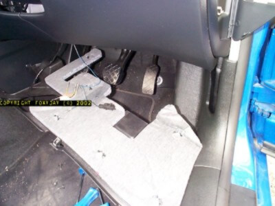
This is the bit which involved dis-assembling the lower part of the dashboard above the drivers foot well.
It’s not a big job, so get a soft pad to kneel on, and your torch handy.
The under-tray to the dash (above the pedals) is secured with seven T20 torx screws.
Carefully pull the panel out and set aside.
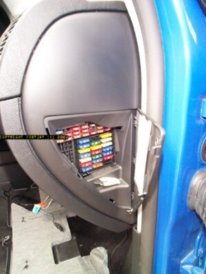
The fuse box is located to the right end of the dash – open the cover and carefully un clip. The end surround, closing off the dash can also be un clipped and all set aside.
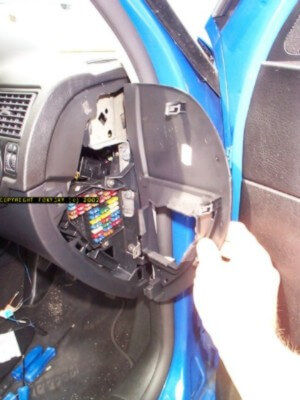
The curved plastic panel below the steering column area can now be removed. Un clip and set aside.
The panel behind this can now be taken out by removing the T20 screws around the outer edges. Set aside once again.
You should now have clear access into the under-dash areas on the driver’s side.
2) Removing the fuse box
The fuse box must be removed from it’s location by undoing two torx bolts.
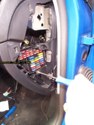
Slide the fuse box down to gain good access to it, and un clip the back cover. Careful! as there are some fuses powered-up when the ignition is off. Stray metal objects could short-out!
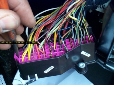
Looking at the back of the fuse box, you will see the purple (magenta) plastic grid, which securely keeps all the terminals in place.
3) Working on the fuse box
You will need to lever this into it’s ‘release’ position with a screwdriver – it should ‘click’ into position.
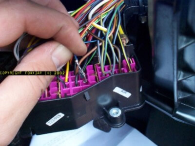
Locate fuse number 5. It is a mini-blade type, and should be 7.5 A rated.
Now, you need to carefully un hook the black/blue striped wired leading to the terminal on the ‘dead’ side of this fuse.
I used an un-wound paper clip of the large variety, and slid the end of the clip wire up beside the terminal, from the front.
The idea is to try and push the ‘barbed’ hooks (two) on both sides of the terminal, so you can pull it out.
With this terminal now removed, splay out the hooks if they were pushed back, and insert the terminal into the loose plastic clip that came with the Cruise Control wiring loom. (Part# 191972701).
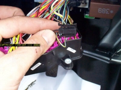
Now click the plug on the end of the loom (Part# 191972711) into this plug behind the fuse box.
Insert the short black/blue cable of the new loom into the now spare fuse 5 chamber. Re-click the purple grid into it’s original position on the back of the fuse box.
Re-assemble the fuse box rear cover, ensuring the new CC wiring loom passes out along with the rest of the cables. Tie them together with a small wire tie.
4) Connecting the wiring loom
Now, thread the ‘loose’ end of the new CC wiring loom (with the bare terminals) in behind the dashboard, following the other wiring routes, and push them up to the location of the main cable socket box.
Working outside now, pull the terminals up through the aperture, and ensure the coloured tags are in place to identify the wires.
Now, taking the black socket, install all the new wiring loom terminals into their respecting numbered positions.
Again, there is a purple securing grid on the back of the socker that will need clicking into it’s alternative position whilst you insert the terminals.
Be careful here to ensure the terminals go into the correct positions on the socket, as the ID numbers are molded into the socket and are quite small.
Once all the terminals are in place, click the purple grid back, and re-seat the socket in it’s holder.
Click all the plugs back into their respective coloured sockets, and re-seat the mounting grid.
Re-install all removed items in the reverse order of removal:
Cable socket box
Wiper mechanism
Scuttle panel
Wiper arms
Bulkead rubber seal
Fuse box
Dash paneling
Under-dash panel
5) Enabling the cruise control
To carry out this final operation, you will need to access the control codes for the ECU.
This can be done in several ways.
- Go to a dealer or specialist with a VW1551 or 1552 tool.
- Use the emulation software by Ross-Tech ( http://www.ross-tech.com/ )
For the latter the following is the ‘generic’ procedure for carrying out this enabling work:
-
- Select engine control module by pressing “01Q”.
- Select read data function by pressing “08Q”.
- Read group 06 by pressing “06Q” or “006Q” depending on which version of VAG 1551 tool that you have.
- The 1551 will display a bunch of numbers. The fourth group of numbers, on the far right of the display will be either “0” or “255”. “0” means that cruise control is already enabled. If you see “255” then cruise control is locked, unlock it using the following steps.
- Press the right arrow key.
- For login procedure press “11Q”.
- Enter the unlock code “11463Q”.
- Now repeat the above steps and see if that “255” has changed to a “0”.
When you switch the cruise control ‘on’ with the new stalk switch, and the ignition is ‘on’, the symbol should alight in the speedo.
Turn the ignition ‘off’, remove the key, then proceed as normal to drive the car.
Ensuring you have a clear open stretch of road, test the controls.
You must have the stalk switch in the ‘on’ position for it to work.
CHECK THE CRUISE CONTROL DISENGAGES WHEN THE BRAKE OR CLUTCH IS PRESSED (be ready to knock it out of gear when testing the clutch switch!)
WELL DONE – IT WASN’T THAT DIFFICULT WAS IT?
Original location:
http://homepage.ntlworld.com/dgace/cruise_control.htm
This web page was posted at the link above but the website is no longer online and I was unable to track the owner down. I felt this web page was too good to disappear.
Learn more about my Revival project, any questions let me know.